

Hello, hope this is the right sub forum for this, being the first post.
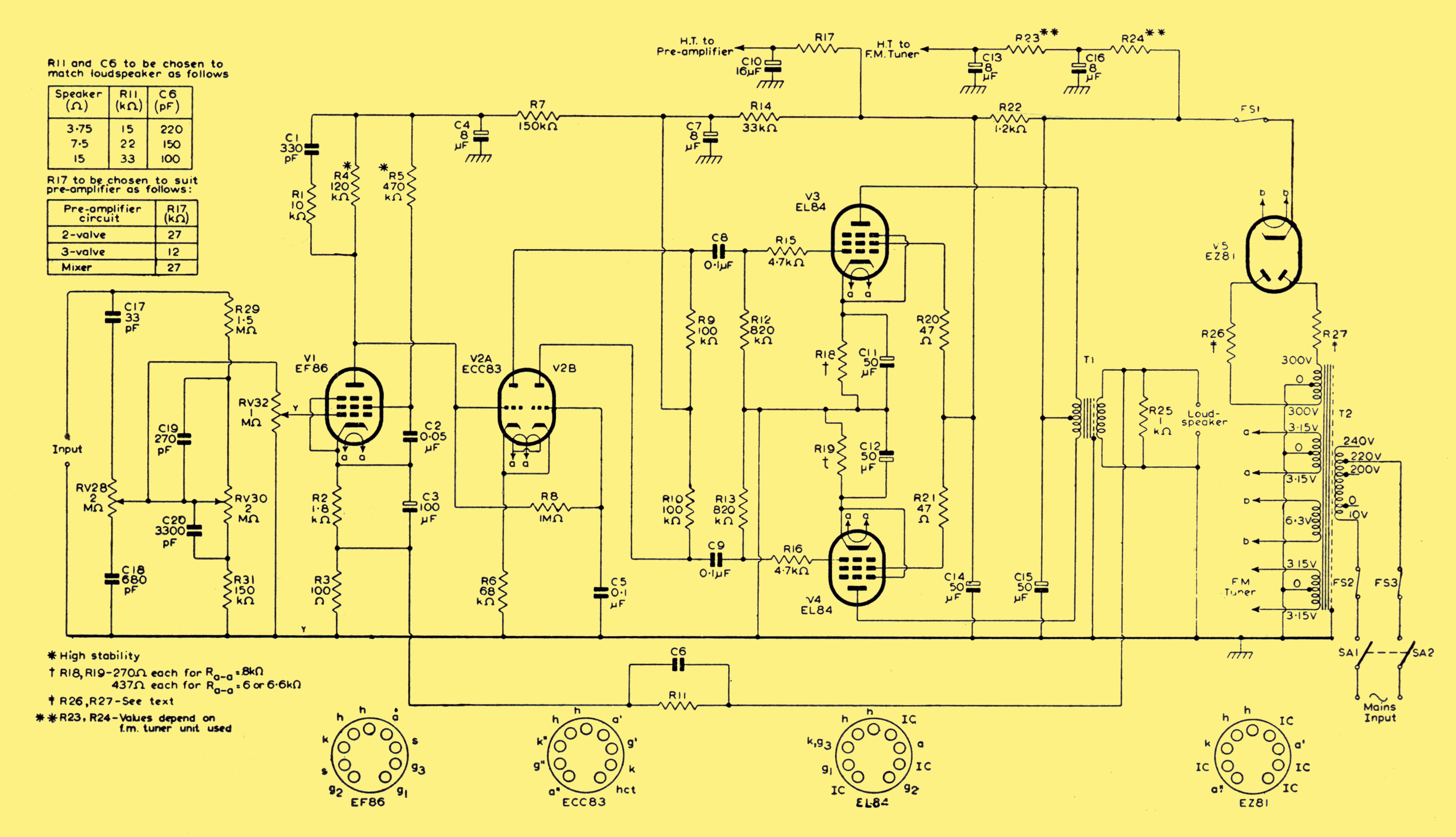
I am doing my first build in many years, reusing chassis and transformers from an old organ amp, originally somewhat similar to this - https://www.r-type.org/articles/art003bca.jpg with a choke input filter and ultralinear screen taps being the main differences. Rebuilding into to something AC15 alike.
I have measured the PT and choke as best I can and PSUD predicts a very flat ~327V after full wave SS rectifier and CLC input filter. Unfortunately I don't have a very good feel for what is acceptable/safe during start up.
Choke - 317R 8.2H
PT - 285-0-285 source R ~ 125R
2 new 50+50uF can caps
If, eg. I simulate 50-choke-50 into a 5k load, I see an initial current spike into C1 of over 2A which then undershoots as the choke current peaks before settling down after about 0.1s to regular spikes of ~275mA. I suppose my question is, what are the key things to look for during start up which are going to be a problem for stressing the old transformer or other components, and how to remedy these problems?
Understanding safe start up behaviour.
-
duncanamps
- Site Admin
- Posts: 43
- Joined: Tue Aug 26, 2025 9:26 pm
Re: Understanding safe start up behaviour.
Hi, and welcome.
I wouldn't worry too much about the current spike, especially for SS rectifiers. The initial design that PSUD2 opens up with is modelled on the power supply from my 4 x 6L6 / 4 x EL34 guitar amp. It hits peaks of around 9 amps from memory. It's only for a few cycles so doesn't get an opportunity to toast anything.
I'd be more concerned with having the choke; this can give a real voltage yo-yo effect on the input, so check that voltages around these areas don't swing wildly out of control on startup. Regular over-voltage on capacitors or rectifiers is likely to reduce reliability.
Regards,
Duncan
I wouldn't worry too much about the current spike, especially for SS rectifiers. The initial design that PSUD2 opens up with is modelled on the power supply from my 4 x 6L6 / 4 x EL34 guitar amp. It hits peaks of around 9 amps from memory. It's only for a few cycles so doesn't get an opportunity to toast anything.
I'd be more concerned with having the choke; this can give a real voltage yo-yo effect on the input, so check that voltages around these areas don't swing wildly out of control on startup. Regular over-voltage on capacitors or rectifiers is likely to reduce reliability.
Regards,
Duncan
Re: Understanding safe start up behaviour.
Thanks Duncan, I think what I'll do is series connect the first 2x50uF can for a 25uF 1000V C1. The inductor voltage does bounce around for a few cycles at nearly full voltage but I think this looks ok in attached sim output.
However, now that I think about it, in the original amp, I believe the plate current was tapped off before the choke as in your bigdemo sample file. I should definitely do this as it's likely the choke is not rated for that current. Do I understand correctly that the higher ripple pre choke is cancelled in a PP output?
What a great program, make your mistakes in the simulator! Very much appreciated.
However, now that I think about it, in the original amp, I believe the plate current was tapped off before the choke as in your bigdemo sample file. I should definitely do this as it's likely the choke is not rated for that current. Do I understand correctly that the higher ripple pre choke is cancelled in a PP output?
What a great program, make your mistakes in the simulator! Very much appreciated.
- Attachments
-
- PSUD_startup.PNG (79.9 KiB) Viewed 6777 times
-
duncanamps
- Site Admin
- Posts: 43
- Joined: Tue Aug 26, 2025 9:26 pm
Re: Understanding safe start up behaviour.
This is generally correct, the Push Pull stage tends to reject power supply ripple along with even order harmonics.Do I understand correctly that the higher ripple pre choke is cancelled in a PP output?
However, you can get the supply rails modulating the output (IMD - Inter Modulation Distortion) so it may manifest itself as a different type of problem.
On your sim, I'd select V(C1) as well - this is the one that will yo-yo around and strain C1 + the rectifiers. If there was one measurement that would get my attention, it would be that one.
ThanksWhat a great program, make your mistakes in the simulator! Very much appreciated.
